The sole purpose of the ALU_tester unit is to provide random data for the inputs of the ALU and to verify the resulting data from the ALU is correct. Instead of creating a large do file to stimulate the inputs of ALU, we utilize HDL Designer's ModuleWare library. ModuleWare components are pre-built dynamic components that can be instanced into any design.
Our blue sub-block currently has no view associated with it.
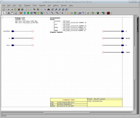
Double-click on the blue block tester so that you may create
a new view. From the window, select Graphical View |
Block Diagram, click Next, then click Finish.
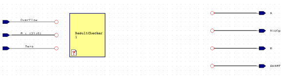
Let's start by adding an embedded block named "ResultChecker".
The purpose of ResultChecker is to read the outputs of
our ALU and check to verify that they are outputting correct
data. Within this block, we will create a flowchart that will
check our results. Remember that a flowchart is a process,
thus it will execute sequentially. Hold off on the flowchart
construction as we have more items to create for the tester.
Your ALU_tester should resemble the figure below:
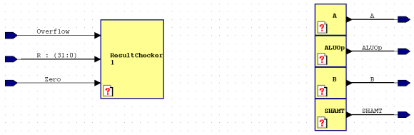
We will now need to add 4 more yellow embedded blocks to our
design. Since output ports cannot be directly read within
the block diagram, we will need to create internal signals
in order to allow our ResultChecker to check the
results with the generated data. The purpose of these
embedded blocks are to assign the internal signals to
the output ports. Being that we do not have the internal
signals created yet, we can come back to this part in a
little.
Let's continue with the construction of the ALU_tester sub-block
by adding the ModuleWare components that will generate our
random data. ModuleWare can be added two ways. You may access
ModuleWare via the menu by clicking Add | ModuleWare...
or by adding the moduleware library in the Componenent
Browser.
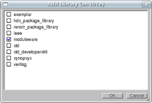
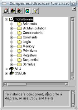
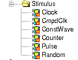
Once access to the ModuleWare library has been gained, We are
interested in the Stimulus section of ModuleWare,
for it is here that we may stimulate the inputs of our ALU. As
you can see from the figure below, there are numerous
components that can provide stimuli. We are obviously
interested in the Random component.
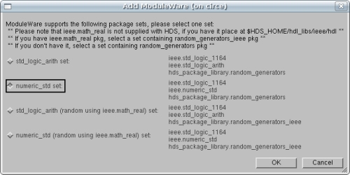
Add the random number generator to your design by left-click-hold
and drag-and-drop the component in your design. In order for
the random number generator to function properly, it will need
additional libraries. Select numeric_std set from the
list, and click OK. If you're interested in what other
functions numeric_std provides, open up the "numeric_std.vhd"
file located in this directory:
"/usr/local/3rdparty/mentor/fpgadv72/Hds/hdl_libs/ieee/hdl"
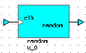
The random number genator will look like the figure below.
Double click on it to observe its properties.
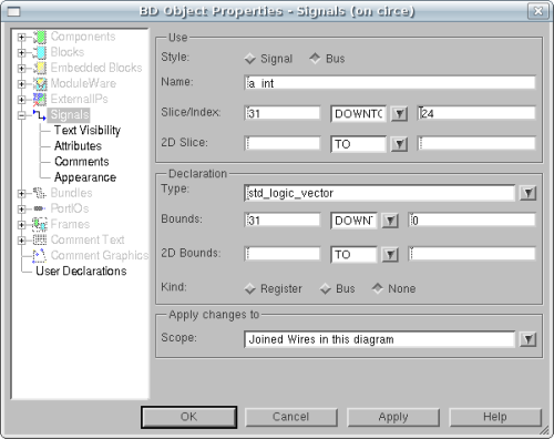
We will be interested in setting 5 properties within
this window. The random generator has the ability to
automatically detect the width of data it needs to
generate. It does this by using the bus width that is
connected to its random port. The only affiliated
problem that the generator has is that it does
not recognize bus slices. For example, the generator
would output 32 bits of data to a connected bus
with bounds (31 downto 0) and a slice of (7 downto 0).
The proper amount of data would be 8 bits. So, to be
safe, we'll manually set the width. The 4 other
properties of interest are Seed, Stop, Number Of Values
and Run Forever. Seed will receive
an UNIQUE arbitrary number were as the rest will receive
specific values. For additional information, please
do not hesitate to click the Details button.
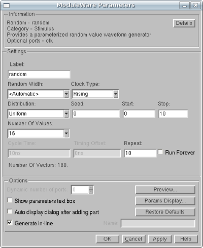
Observe the Number Of Values that the random
generator offers. It has a maximum of 1024 values which
equates to 2^10, thus a maximum of 10 bits. Being that
we have inputs on our ALU that require 32 bits of data,
we must combine multiple generators to create the 32
bits of data. To make things even, we'll use 4 8-bit
generators for outputs A and B of our tester.
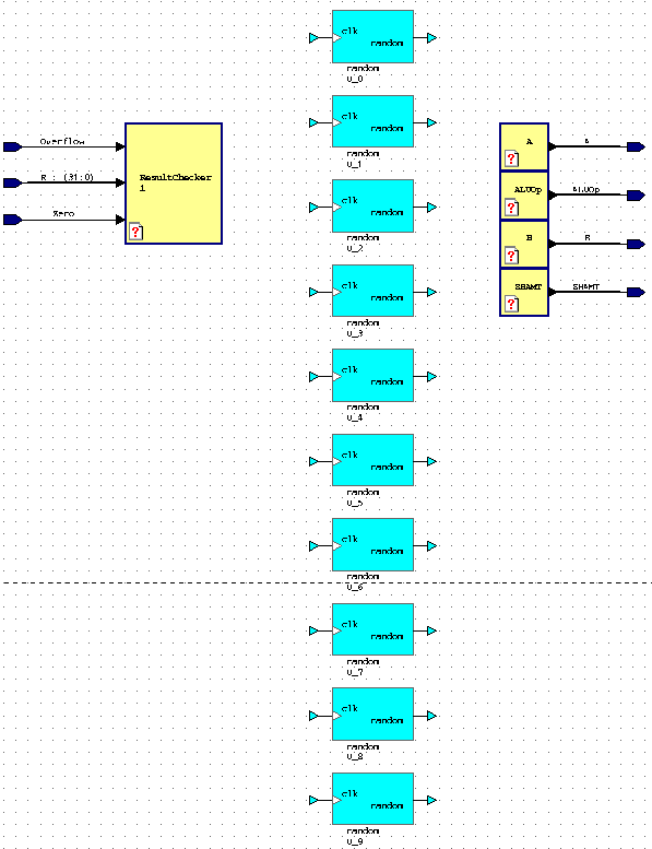
We'll also need a random generator each for outputs
SHAMT and ALUOp. Therefore we need a total
of 10, so add 9 more generators. You may copy/paste 9 in
or drag 9 from the Component Browser. Your figure
should resemble the one below:
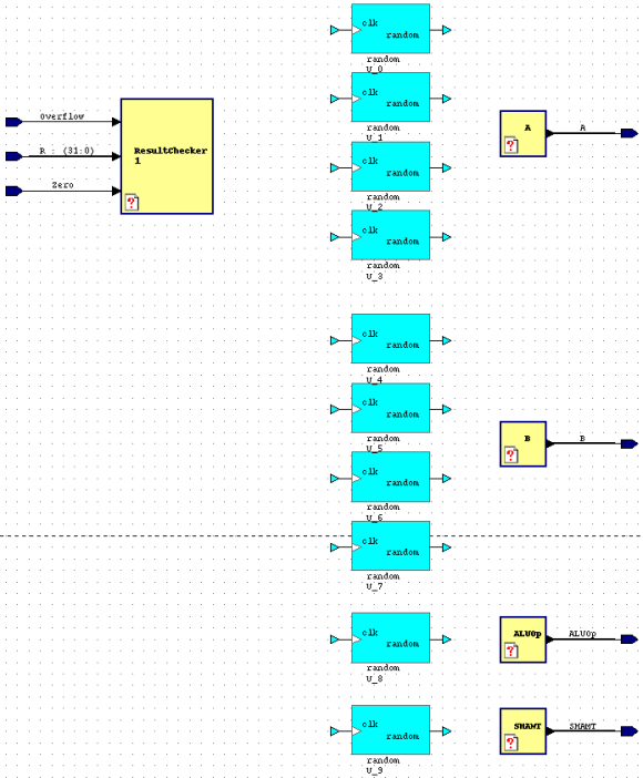
Rearrange your diagram so that it resembles for the figure
below:
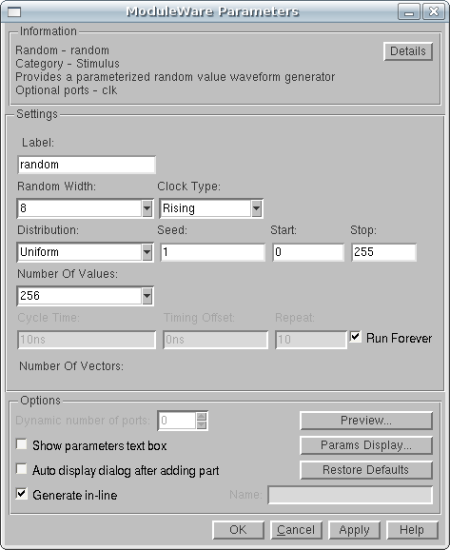
Let's now set the properties for all random generators.
(Remember that each random generator for A and B
will have widthes of 8 bits.) Set every generator with
some unique arbitrary seed number, set the Stop to a
large number (1000+),
set the Number Of Values to 2 or 3 * (2 ^ bus width) and then
select "Run Forever". Click OK and proceed to
configure the rest. The Number of Values is associated
with how many values are randomly generated. Because it's possible
that some values might not be generated, we want to ensure they are
so we increase the Number of Values. Our Stop value
must also be larger so that the amount of sequences will cover all
our values.
Now it's time to connect all the random generators to the
embedded block and ensure bus widthes are correct. Remember
that A and B need 4 random generators each and that they
will have 8 bit slices connecting them to the embedded block.
The order does not matter (31 downto 24 ... 7 downto 0
or 7 downto 0 ... 31 downto 24),
just make sure each slice is connected to only one
random generator. Append the text "_int" to each bus that
indicates to us that it is internal. (a_int, b_int, shamt_int
and aluop_int)
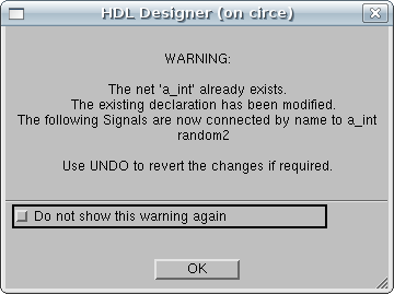
You will receive a WARNING message after setting
second,third and fourth slices. You may disregard these
messages.
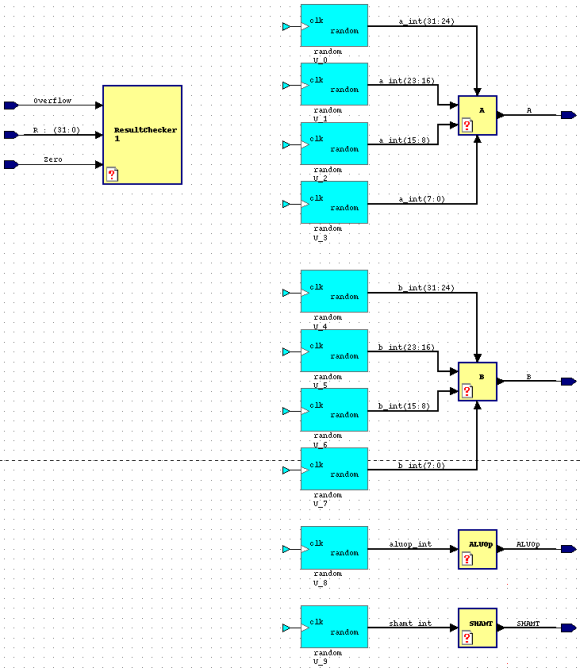
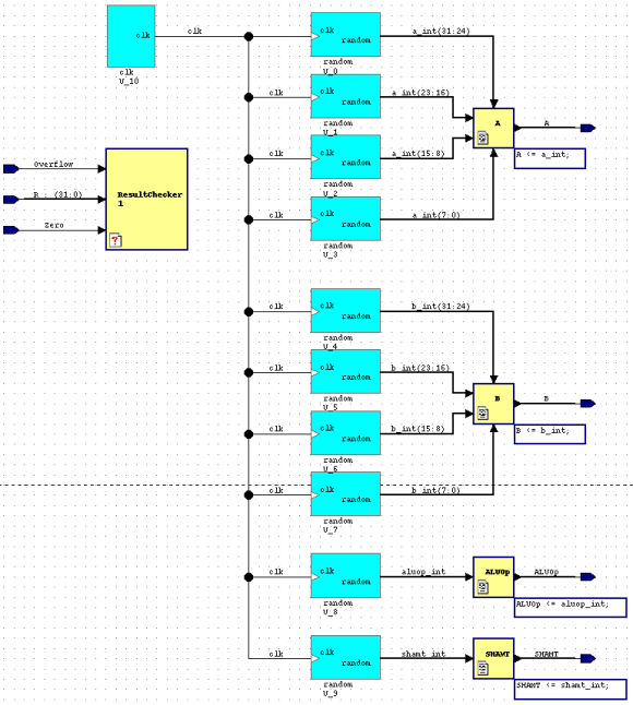
With all the random generators connected via data buses,
your design should resemble the figure below:
We may now assign our internal signals to the output
ports. We achieve this with the yellow embedded blocks.
Double-Click each yellow block, create a text view and
type in the associated command to assign the signal to
the output.
     A <= a_int;
     B <= b_int;
     ALUOp <= aluop_int;
     SHAMT <= shamt_int;
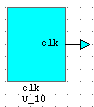
From the random generators symbol, we can ascertain that it
needs a clock input. To make our lives easier, we can
instance a Clock generator from the ModuleWare
library. Using an internal clock generator in our tester
allows to skip the task of always "forcing" the clock
signal on each test attempt. In the the Component
Browser, drag over a Clock generator from
the moduleware library.
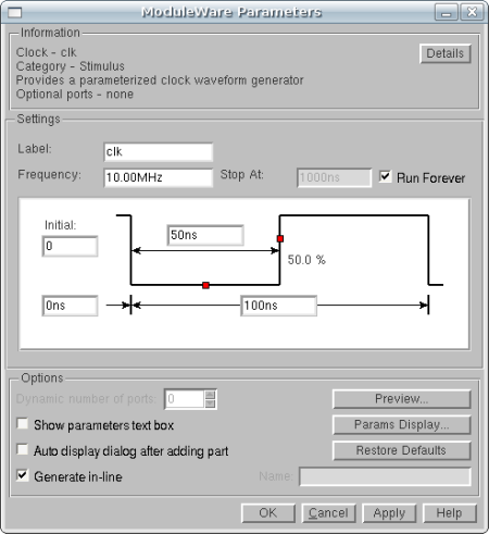
Double-Click the Clock generator so that we may
configure it. You may adjust the frequency as you desire,
but the only requirement is to select Run Forever.
Click OK when complete.
You may finally draw the signal from the Clock
generator to the Random generators that require
it. Your design should finally resemble the figure
below:
We have completed the data generation that will be used
to test our ALU. Our next step is to design the
ResultChecker which will verify the output results with
the inputs that the ALU sends/receives.