Given the complexity of large scale digital designs, it is estimated that more the 50% of the total design time for a new device is spent on testing and validation. Just think a little about the way you have tested your designs so far. You created a script file with a set of cases representing each function that you wanted to test, you ran the script and then looked at the output data to manually verify that the actual output was what you expected. Some of those script files were fairly long, yet they typically tested only one case for each of the functions that you wanted to test. What if you wanted to test every possible case? For addition, this would mean testing 2**32 input combinations, a seriously long script file.
Instead of thinking of testing on a case-by-case basis let's think
about testing as validating the behavior of the circuit. For example
instead of testing if the addition function works by asking if 2+2=4,
let's make an assertion about the relationship between the
inputs and the outputs. For example as ASSERTION about an adder would
test the PROPERTY, A+B = R. In the context of testing, an ASSERTION
is a statement about the expected behavior (called a PROPERTY)
of the circuit.
Assertions can take many forms. They can test properties that
must always hold, or never hold. For example:
Assert NEVER, Property ALUop = "1000" ----Since 1000 is an unassigned operation code.
Assertions can test relationships between multiple inputs and
outputs:
Assert IMPLICATION Property WHEN ALUop = 0011 THEN R = A+B.
Assertions are most powerful for test timing and sequence
relationships (although these will not be useful for testing
your ALU, we will see this in detail in the memory bus)
Assert SEQUENCE Property A,B,C
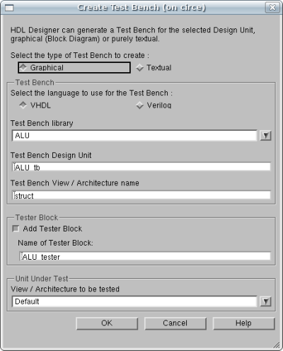
Let's begin by creating our Test Bench that will facilitate
our testing of the ALU. This can be achieved with the following
two methods. First you must with a single Left-Click select
the ALU component in the Design manager. You may then
either via the menu click File | New |
Test Bench or Right-Click the ALU and then
select New | Test Bench. Click OK
to proceed.
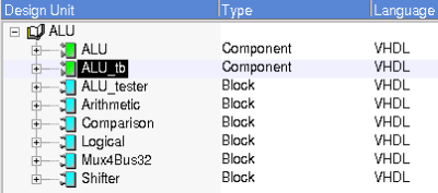
You should now see a green component created in your design
named "ALU_tb". Double-clicking on "ALU_tb" will show you
the test bench that was generated according to your
design.
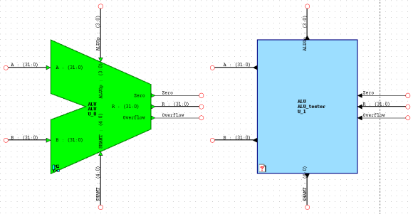
As you can see from the block diagram that was created, an
instance of your ALU has been instantiated along with a blue
block. Notice that the signals that are outputs from your design
component (in green) have the same name as those which are
input into the blue sub-block called ALU_tester and vice-versa. We
have not seen this before, but another feature of the Block
Diagram Editor is that signals of the same name are the
same signal, even if they are not visually connected together.
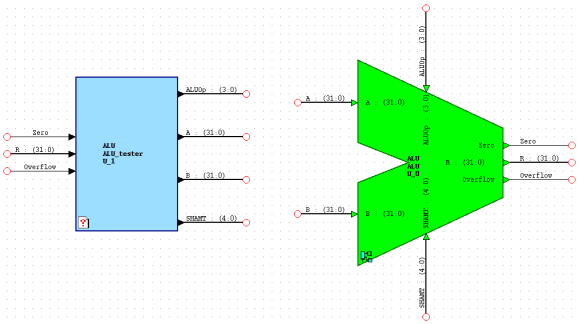
You may resize and rearrange your testbench for better readability.
This of course is purely aesthetical and can be done any way the
student wishes. The figure below demonstrates a reorganized view
of the two blocks:
Although our Test Bench has been automatically generated for us,
we lack the logic that it requires to test our components. We
shall now proceed to creating the ALU_tester's functionality.