| Operation | ALUOp(1) | ALUOp(0) |
|---|---|---|
| SLL | 0 | 0 |
| SLA -> N/A | 0 | 1 |
| SRL | 1 | 0 |
| SRA | 1 | 1 |
Implementing the Shifter with a Flowchart
We will be implementing the Shifter block with a Flowchart view. A flowchart view creates a VHDL process block containing sequential statements to describe the behavior. Sequential VHDL statements can only be found within special constructs called processes. Within a process, these statements are executed, as the name implies, sequentially. They consist of such statements as if..then..else, case, and wait.
To begin, first we need to create a Flowchart View
for the Shifter sub-block in the ALU block
diagram. Do this by double-clicking on the Shifter sub-block
in the ALU design window and select Flowchart in
the window that appears. Click Next and then Finish.
An empty flowchart will be created similar to diagram below:
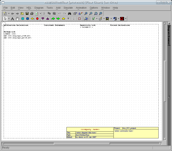
You will notice that there are no ports or signals
visible on the flowchart. This is because this is a
purely behavioral description of the block, with no
structural elements as in the block diagram view. All
of the signals which are connected to the sub-block
in the ALU block diagram will be visible within
the process. You will have to remember them though.
At the top of the design area, there are four boldface
headings:
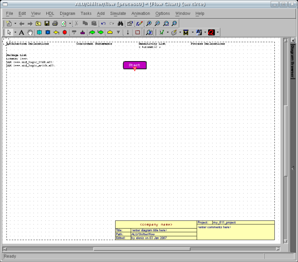
Since a process is sequential, it lends itself to a flowchart
representation. The first step in creating the flowchart is
to place a Start block on the design area by activating
the Add Start Point tool,  . Click
on the flowchart to add the start point.
. Click
on the flowchart to add the start point.
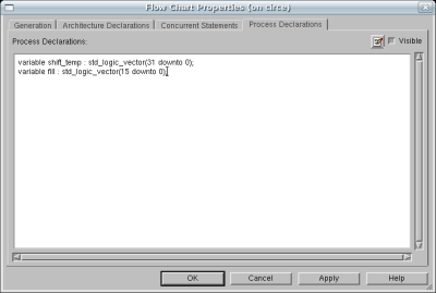
The first thing we need to do is add the process declarations
necessary for our shifter. We add the process declarations by
right-clicking over an empty spot of the flowchart and selecting Flow Chart
Properties from the pop-up menu. Select the Process
Declarations tab and type the declaration in the white
text area:
	variable shift_temp : std_logic_vector(31 downto 0);
	variable fill : std_logic_vector(15 downto 0);
Click OK when you are done. Note: You can also double-click on the bold Process Declarations title at the top of your flowchart in order to add/remove declarations.
These variables are an integral part of our flow chart's operation.
Variable shift_temp will be used to store any intermediate results
during the shift operation and will contain the final result at the
end of the shifting. The fill variable will contain the proper bit
that will be shifted into the shift_temp variable.
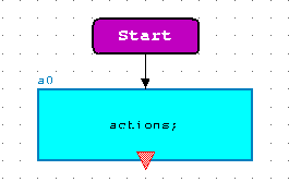
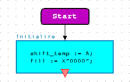
The next thing we want to do is to create an action box so
that we may initialize our variables that we created. To do this
we use the Add Action Box tool,  .
This will create a blue box that will allow us to enter the
actions we wish to execute.
.
This will create a blue box that will allow us to enter the
actions we wish to execute.
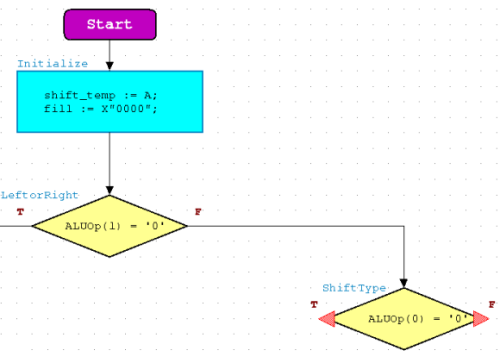
We want to initially set our shift_temp variable to input A and
the fill variable to all 0's in order to satisfy a logical
shift operation. To do this, double-click the actions text and type
in the actions required. Also, rename the default name a0
to Initialize.
Note: It is important to remember that variables have a different
opperator symbol := unlike the <= operator symbol that signals use.
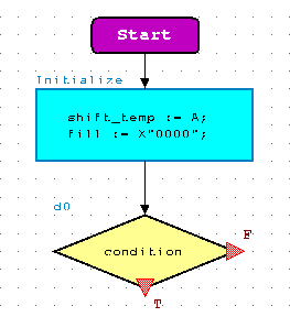
The next thing that we want to do is to decide whether we
are shifting left or shifting right. To do this, we will need to
place a decision box into the design just below the action
block using the Add Decision Box tool,
 . This will add a yellow
diamond to the flowchart with reddish triangles at two of
its points labelled T for TRUE and F for FALSE.
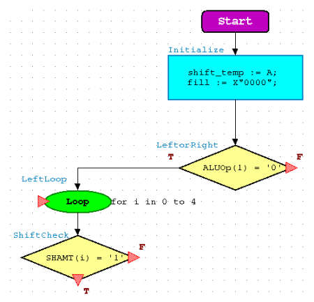
The flowchart will now look like the figure below:
. This will add a yellow
diamond to the flowchart with reddish triangles at two of
its points labelled T for TRUE and F for FALSE.
The flowchart will now look like the figure below:
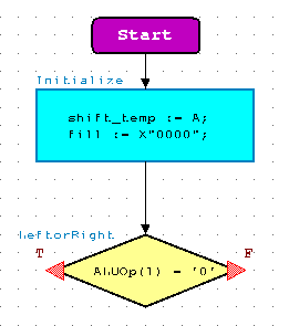
We have added a decision box, but we haven't yet told it
which decision to make. To do this, we need to enter an
expression which evaluates to TRUE or FALSE inside the
decision box in place of the text labelled condition.
Since ALUOp(1) specifies the Left/Right shifting, we will
enter ALUOp(1) = '0' as the condition. Now if
we are shifting left, and ALUOp(1) = '0', we will follow the
TRUE branch, otherwise we will be following the FALSE branch
which will perform a right shift.
To even things out visually, we will also move the TRUE branch
source, the small reddish triangle labelled T, to
the left corner of the yellow diamond. Finally, rename the
decision box by highlighting the default name d0 and
entering LeftorRight Your flowchart should look like
figure below:
Left Shift Operation
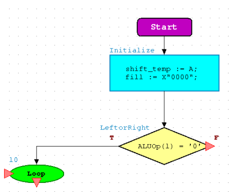
We will now go on to filling in the left-hand branch of this decision, implementing the left-shift. This operation will obviously take place if ALUOp(1)='0' is TRUE. This shift operation is going to be implemented in stages via a Loop. We will begin by looking at bit 0 of the SHAMT. If it is a one, then we will be shifting left by one bit into our variable shift_temp. Otherwise, we will simply bypass the shift operation and continue with the loop.
Our first step is to add the Loop's start point, just like like the Do
statement of a Do/Loop. Click on the Add Start Loop button,
 , and place it so that is connects to
the True triangle of the LeftOrRight Decision Box. An outline of
the Loop will follow your cursor until you single left-click onto your
workspace. If you unsatisfied by its placement, simply drag to a new spot.
, and place it so that is connects to
the True triangle of the LeftOrRight Decision Box. An outline of
the Loop will follow your cursor until you single left-click onto your
workspace. If you unsatisfied by its placement, simply drag to a new spot.
With our Start Loop in place, we can now add the loop logic to it.
To do this, you must first double-click on the Loop object. Initially,
the Loop's Control will be set to Forever. Since we do not want
our loop to continue forever, we will specify its operative properties.
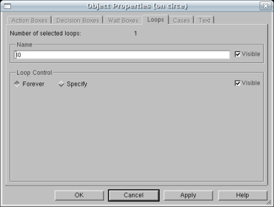
Click Specify and you will be presented with two boxes. The top box
is for you to enter your custom loop with the bottom box presenting examples.
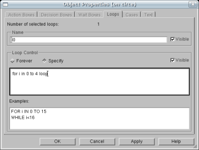
We want our loop to cycle 5 times before ending. To do so, type the following
into the box: "for i in 0 to 4 loop". Your Object Properties should resemble
the figure below. Click OK when you're complete.
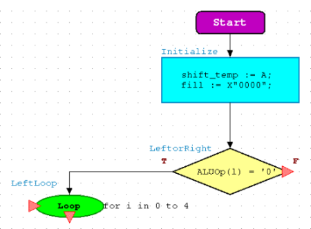
The purpose of the 5 loop iterations is to evaluate the 5 bits
of SHAMT. If SHAMT(i) = '1', then we know that we are supposed to
shift our data the amount associated with the bit's location.
Rename "l0" to "LeftLoop" and you may move your "for i in 0 to 4 loop"
statement if you do not like it's position.
We will now need to evaulate SHAMT for the prescence of a '1' in each
of its bits. Add a Decision Box so that it resembles the following figure:
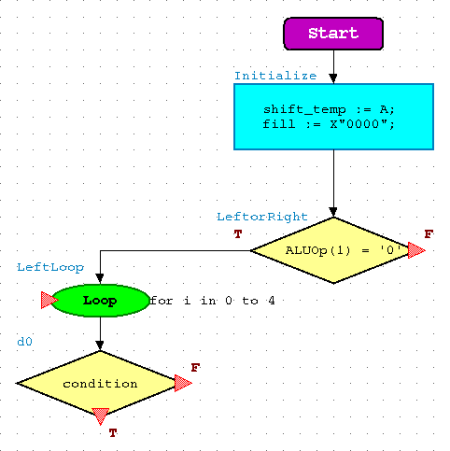
We may now set the condition statement for the purposes of our SHAMT
evaluation. Thanks to the 5 iterations of the loop via the "i", we can
evaluate all 5 bits of SHAMT. Your Decision Box should resemble
the figure below:
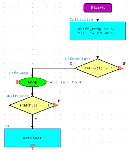
If our condition should prove to be TRUE, we will want to implement a
shift. So, add an Action Box to house our required action(s)
for a shift.
Our shift will require both of our variables that we declared
earlier. Shift_temp will not only contain the value we are
shifting, but will also store our intermediate shift results while
fill will contain the bits that will be shifted into the
right side. Since the Left Shift is only Logical, we do not have
to worry about shifting in the proper sign bit. The current value
of the fill variable of all 0's is fine.
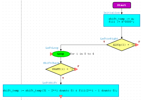
The shift operation will be executed with one statement and will achieve
3 things during its execution. It will first take the 32 bit value of
shift_temp and reduce its size by 2^i. For example, if "i" was 0,
shift_temp would now be 31 bits due to the operation because 32 - 2^0
is 31. The most significant bits get dropped in a Shift Left Logical.
The second part of the operation is to append 2^i fill bits
to shift_temp so that it is 32 bits once again. The bits will be
appended to the least significant bit side of shift_temp. The
third and last step to this operation is to store the new results back
into shift_temp. Observe the figure below to complete your
Action Box.
We are now done with the contents of the loop and must add an end
point to the loop. To do this, we click the Add End Loop button,
 , and place it after our LeftShift
Action Box. You may also move the flow arrow so that it is not
going through your Action Box. This is purely for cosmetics only.
Your flow diagram should resemble the one below:
, and place it after our LeftShift
Action Box. You may also move the flow arrow so that it is not
going through your Action Box. This is purely for cosmetics only.
Your flow diagram should resemble the one below:
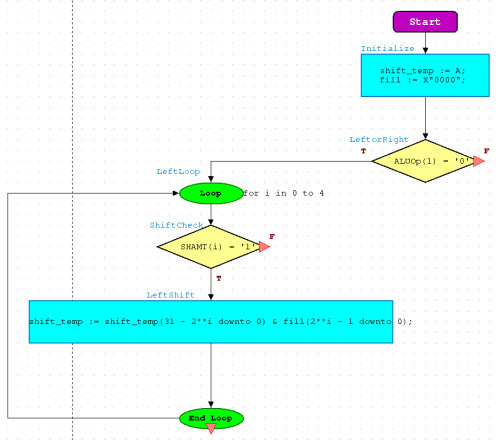
The last thing we need to do is ensure that our loop operation is
complete. At this current moment, it is not. Our ShiftCheck
Action Box has only its TRUE condition with a flow. If condition
was FALSE, there would be continuance of flow and the loop would not
increment to the next value of "i". We must fix this flaw. To do so,
we will add a flow that will connect with the flow coming out of LeftShift.
Click the Add Flow button,  and draw a flow from the FALSE condition of ShiftCheck to the output flow
of LeftShift. Your diagram should look as follows:
and draw a flow from the FALSE condition of ShiftCheck to the output flow
of LeftShift. Your diagram should look as follows:

The left of our flow diagram is now complete. Please remember to save your work
periodically.
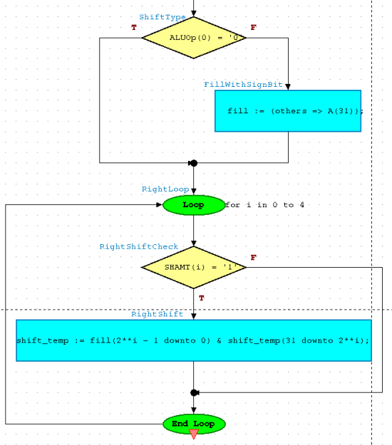
Right Shift Operation
Filling in the right shifting half of the flowchart will be very similar to filling in the left half. The only difference will be that we need to account for a possible arithmetic shift. This will require an extra Decision Box at the top of the right branch to determine what values to shift into the vacated bits. The Decision Box will check the ALUOp(0) bit to determine logical or arithmetic shift operation.
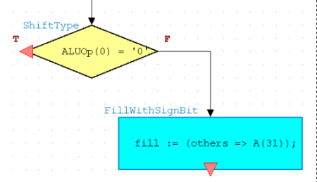
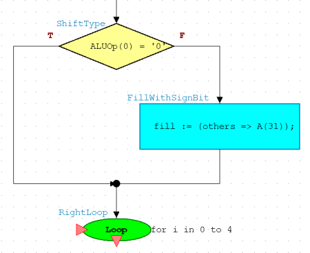
You may begin by adding a Decision Box to check the shift
type.
If ALUOp(0) = '0' is TRUE, our shift operation will be Logical
and will not require our fill variable to be altered
since it already contains 0's. If the condition proves to be
FALSE, our shift operation will be Arithmetic can not rely the
contents of our fill variable. To rectify the situation,
the fill variable that we previously declared will have
to be filled with the sign bit of A.
Continue by adding an Action Box to execute the command
required. Our Action Box will set all elements of the fill
variable that were not explicitly listed to A(31), which is the
sign bit. Since we did not explicity list any portions of fill,
every bit will be set to the value of A(31). Change the name
from "a0" to "FillWithSignBit".
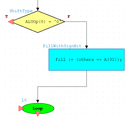
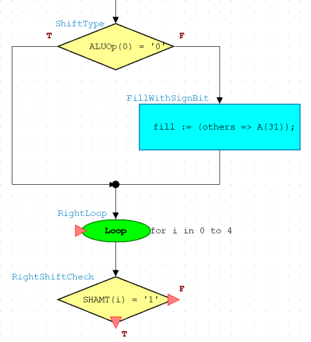
With the fill variable taken care of, the operation will closely
reflect that of the Left shift. Once more, add a Start Loop so that your
figure resembles the following:
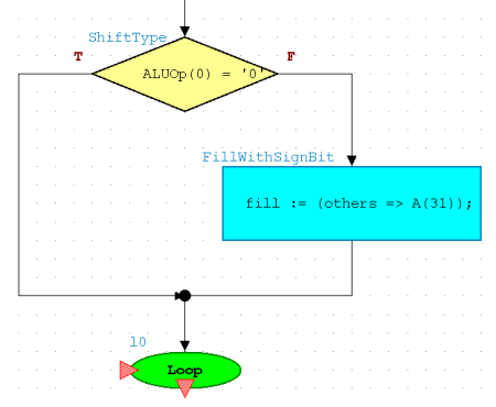
Once again, we must ensure that our flow continues so that our
operation is not disrupted. Add a flow from the TRUE side of
ShiftType to the output of FullWithSignBit. Now a TRUE statement
will continue to shift instead of do nothing.
Double-click the start loop point and modify it again just as
you did for the LeftLoop. This time, name it RightLoop.
Add a Decision Box so that we may check the SHAMT.
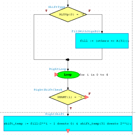
This is the only difference between the left and right
shift operation. It will still consist of a single statement that
will achieve 3 things. The main difference is where the fill
bits will be appended. This time, the fill bits will be appended
in front of the most significant bit of shift_temp. Add an
Action Box and use the following figure for reference:
Now add an End Loop to your flow chart so that the shift may
go through its 5 iterations. You may once again move the flow
so that it is not going through the RightShift Action Box.
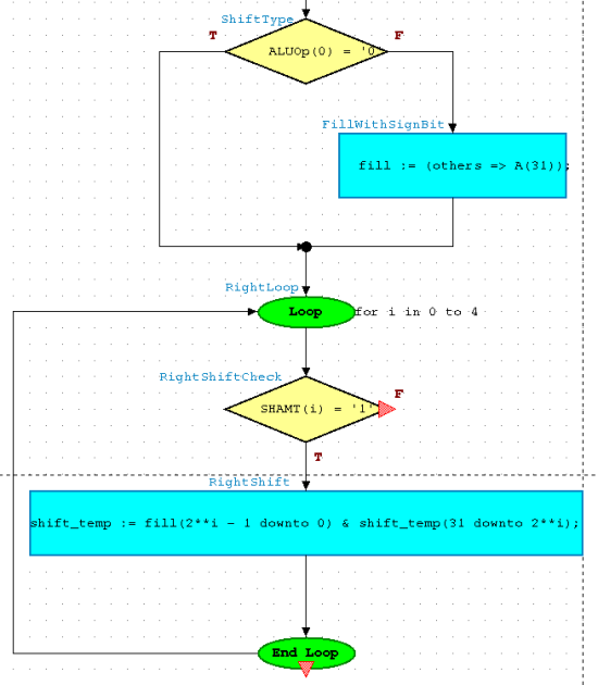
Complete the flow of the loop once again so that it will not be
stuck. Add a flow from RightShiftCheck to the output of RightShift.
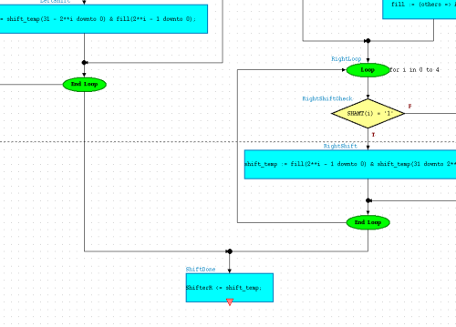
Completing the Flow Chart
We are almost done with our flow chart. At the end of each of the loops, our shift_temp variable will contain the final result. Since the variable is internal, we must assign its value to a signal. Add an Action Box to one of the End Loops. From the End Loop that is not connected to the Action Box, add a flow from it to the Action Box. Now we can set the action to assign shift_temp to our signal ShifterR.
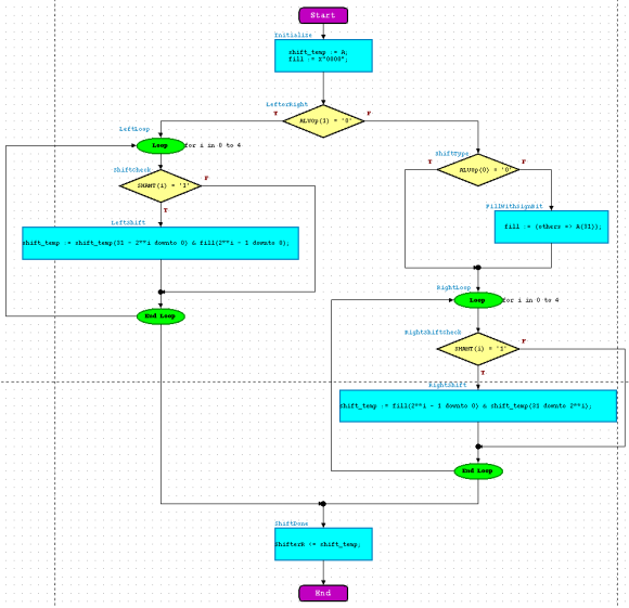
Our last step is to add the end point. You can do this by clicking the
Add End Point button,  , and
placing it after our ShiftDone Action Box. Your entire flow chart
should resemble the figure below:
, and
placing it after our ShiftDone Action Box. Your entire flow chart
should resemble the figure below:
Also, make sure you assign signals(i.e. ShifterR) using the <= operator
and variables (i.e. shift_temp) with the := operator!
When you have completed the flowchart for the Shifter sub-block as
outlined above, you are ready to..