All that remains to do to complete the ALU block diagram is to specify the Mux4Bus32 sub-block. In the Logical sub-block, we accomplished this by placing an embedded block with a VHDL statement to multiplex the signals. For this sub-block, we will use similar VHDL statement, only we will enter it directly as a text VHDL Architecture description.
Open the ALU block diagram and double-click on
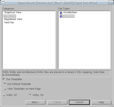
the Mux4Bus32 sub-block. From the window which appears
select VHDL File from the left pane. The right pane will appear
with two file types, select VHDL Combined and click Next.
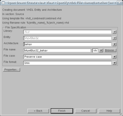
Enter behav as the name of the view and click Finish.
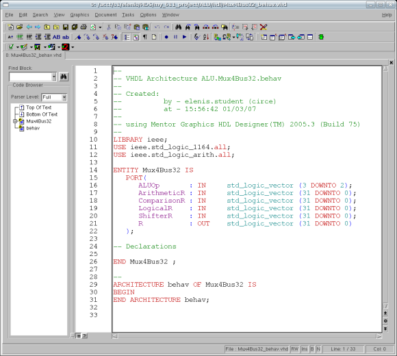
This will bring up a VHDL Editor with the skeleton
VHDL Architecture declaration seen in the diagram below:
Now, just as in the embedded block, we will be using a
conditional assignment statement to infer the multiplexor.
The conditional assignment statment has the syntax:
	TargetSignal <= SourceSignalA when (ConditionA) else
			SourceSignalB when (ConditionB) else
			...
			SourceSignalZ;
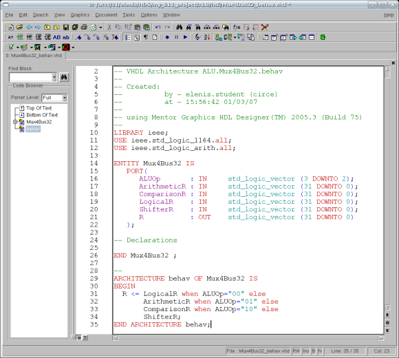
In this case, the target signal is R and there are four source signals: LogicalR when ALUOp(3 DOWNTO 2) is "00"; ArithmeticR when ALUOp(3 DOWNTO 2) is "01"; ComparisonR when ALUOp(3 DOWNTO 2) is "10"; and ShifterR otherwise (when ALUOp(3 DOWNTO 2) is "11").
The conditional signal assigment statement can be a
concurrent statement, meaning it can be at the top level
of an architecture outside of any processes. Since this
is the only statement necessary to describe the funcionality
of the Mux4B64 sub-block, the VHDL Architecture
should look something like Figure 2. Note that if you are
assigning the value of one std_logic_vector to another of
the same size (R and LogicalR for example)
then you can omit the slice information.
Once you have entered the text properly, save the file
and exit the VHDL Editor. You can now proceed to...