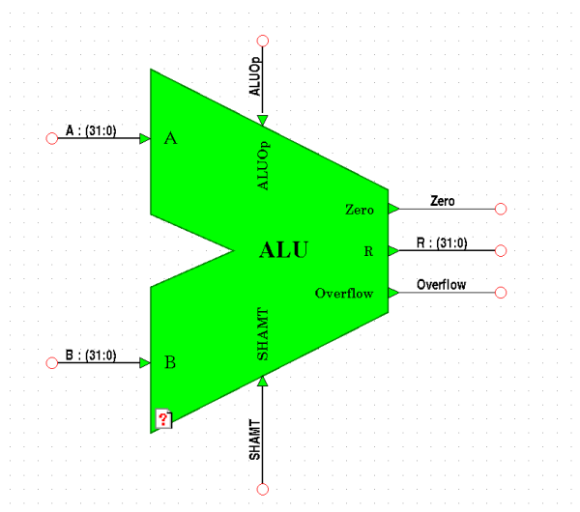
Before we begin the tutorial, this page will provide a black box description of the device that you will design. What you see in the figure below, is an external description of the device called a symbol in the Mentor tools. This is the basic method for implementing hierarchical designs and for supporting design abstraction. The symbol tells us the input and output specification, but we have no way of knowing what is going on inside. In fact, over the course of the design we may use several design descriptions interchangeably the same way that several architectural descriptions may be provided for a single entity descriptions in VHDL. In fact this is the graphical equivalent of the entity statement in VHDL.
For the purposes of this tutorial, the I/O architecture is fixed by the processor design from your text. The signal type and direction of each signal is described in the following table.
| INPUTS | Descriptions |
|---|---|
| A (31 downto 0) | Operand A is a 32 bit input bus carrying the "A" operand for an ALU operation. |
| B (31 downto 0) | Operand B is a 32 bit input bus carrying the "B" operand for an ALU operation. |
| ALUOp(3 downto 0) | ALUOp is a 4 bit input bus which controls which operation the ALU executes. |
| SHAMT(4 downto 0) | SHAMT is a 5 bit input bus which forms the shift amount. The 5 bit shift amount indicates the number of bits to shift the operand in a shift operation. |
| OUTPUTS | Descriptions |
|---|---|
| R(31 downto 0) | R is a 32 bit output bus which will hold the result of the ALU Operation. |
| Zero | Zero is a single bit output which will be set high if the result of an arithmetic operation is equal to zero and low otherwise. |
| Overflow | Overflow is a single bit output which will be set high if the execution of an arithmetic operation results in an overflow of the adder/subtractor and low otherwise. |
For reference as you implement the design, the functionality of the
ALU is listed below. As above, these functions have been determined by the
hardware operations of the MIPS R2000 instruction set and the role of the
ALU in each operation. We will look into this process in detail when we
design the control unit for our microprocessor. For now, we will assume
that we have been handed a set of specfications that describe the set of
functions that the ALU must implement. They will be encoded on to the ALUOp
and the SHAMT input.
| Name of Operation | Description of Operation |
|---|---|
| Add Signed (ADD) | R = A + B : Treating A, B, and R as signed two's complement integers. |
| Add Unsigned (ADDU) | R = A + B : Treating A, B, and R as unsigned integers. |
| Bitwise AND (AND) | R(i) = A(i) AND B(i). |
| Bitwise NOR (NOR) | R(i) = A(i) NOR B(i). |
| Bitwise OR (OR) | R(i) = A(i) OR B(i). |
| Set on Less Than (SLT) | R = "000...01" if A < B otherwise R = "000....00" : Treating A and B as signed two's-complement integers. |
| Set on Less Than Unsigned(SLTU) | R = "000....01" if A < B otherwise R = "000....00" : Treating A and B as unsigned integers. |
| Shift Left Logical (SLL) | R = A << (SHAMT) : filling in vacated bits with '0'. |
| Shift Right Arithmetic (SRA) | R = A >> (SHAMT) : filling in vacated bits with replicas of the sign bit, A(63). |
| Shift Right Logical (SRL) | R = A >> (SHAMT) : filling in vacated bits with '0'. |
| Subtract Signed (SUB) | R = A - B : Treating A, B, and R as signed two's complement integers. |
| Subtract Unsigned (SUBU) | R = A - B : Treating A, B, and R as unsigned integers. |
| Bitwise XOR (XOR) | R(i) = A(i) XOR B(i). |
Our ALU has been designed such that an individual can
infer the op codes by observing the layout of the design.
As you continue through the tutorials, you shall see that
you'll be able to determine what ALUOp code does what
without consulting a table. The following table for quick
reference:
| ALU Op Code | Operation |
|---|---|
0000 |
AND |
0001 |
OR |
0010 |
XOR |
0011 |
NOR |
0100 |
ADD |
0101 |
ADDU |
0110 |
SUB |
0111 |
SUBU |
1000 |
N/A |
1001 |
N/A |
1010 |
SLT |
1011 |
SLTU |
1100 |
SLL |
1101 |
N/A |
1110 |
SRL |
1111 |
SRA |
We are now ready to start up to tools and set up your design libraries.