[print this page]
Adding Ports, Signals, and Busses to the Block Diagram
First, go to the Add Bus button on the toolbar,
 , and click the arrow just to the
right. Select the Bus with Port option,
, and click the arrow just to the
right. Select the Bus with Port option,  .
Now make sure the Add Bus button is highlighted, or selected,
if not left-click on it to do so. Now when you move the mouse over the
design area you will see the pointer is now a crosshair. Left-click once
with the left button near the left hand side of the design area to begin
drawing a bus. If you move the pointer you will see the outline of an input port
with a bus extending out of it to the point where the pointer currently is.
Move the pointer to the right six or seven grid spaces and double-click
with the left button to terminate the bus with a dangling net connector,
which will be represented by an open circle at the end of the bus. The left
hand side of the bus should have an input port attached to it and the right
hand side should end in an open circle, meaning it is not yet connected to
anything. Also a default name, dbus0, has been assigned to the
bus with a default type std_logic_vector(31 DOWNTO 0) and this has
been added to the Declarations list.
.
Now make sure the Add Bus button is highlighted, or selected,
if not left-click on it to do so. Now when you move the mouse over the
design area you will see the pointer is now a crosshair. Left-click once
with the left button near the left hand side of the design area to begin
drawing a bus. If you move the pointer you will see the outline of an input port
with a bus extending out of it to the point where the pointer currently is.
Move the pointer to the right six or seven grid spaces and double-click
with the left button to terminate the bus with a dangling net connector,
which will be represented by an open circle at the end of the bus. The left
hand side of the bus should have an input port attached to it and the right
hand side should end in an open circle, meaning it is not yet connected to
anything. Also a default name, dbus0, has been assigned to the
bus with a default type std_logic_vector(31 DOWNTO 0) and this has
been added to the Declarations list.
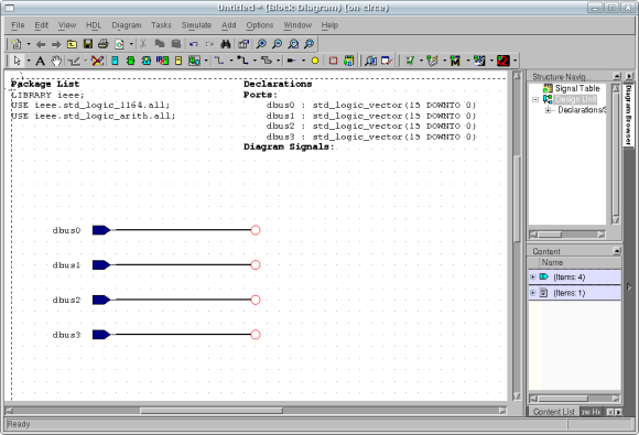
By default, the Add Bus button will remain active until you
press the Escape key or click with the right mouse button or on
another button on the toolbar. While it remains active, add three
more busses to the diagram below the first one so that it looks
something like the figure below. Space your ports and busses at least
two to three grid spaces apart.
You may move the bus around on the block diagram by making sure that
the selection tool,  , is active and then
pressing and holding the left mouse button over a point in the middle of
the bus and dragging it to the new position. You should see the outline
of the bus as you drag and reposition it. You may make the bus longer
or shorter at this point by pressing and holding the left mouse button
over the dangling net connector circle and dragging it to the new location.
, is active and then
pressing and holding the left mouse button over a point in the middle of
the bus and dragging it to the new position. You should see the outline
of the bus as you drag and reposition it. You may make the bus longer
or shorter at this point by pressing and holding the left mouse button
over the dangling net connector circle and dragging it to the new location.
The Add Bus button, unfortunately, cannot be used to add an
output port in the manner described above. Before adding the output
ports, resize the design area so that it extends almost the width of
the screen. This way we can add output ports at the far right and
have plenty of room in between to place the blocks which will give the
ALU its functionality. You can resize your design area by zooming out and
there are quite a few ways. If you observe the toolbar, you'll see a series
of magnifying glasses. Click on the Zoom Out button,  ,
until you reach your desired view. The quickest and easiest method is to
utilize your middle-click button if you have a mouse with a wheel scroll.
Middle-click and hold the button down. While holding the button, move your
mouse in a slow circular pattern and observe all the zoom functions you
can achieve just with your middle mouse button.
,
until you reach your desired view. The quickest and easiest method is to
utilize your middle-click button if you have a mouse with a wheel scroll.
Middle-click and hold the button down. While holding the button, move your
mouse in a slow circular pattern and observe all the zoom functions you
can achieve just with your middle mouse button.
In order to add an output port click on the arrow of the "Add Port" button
 . Select the Add Port Out.
Now move the pointer to the right hand side of the design area and place an
output port in the design. While the tool is still active, place two more
output ports, making sure to leave at least two vertical grid dots between each port.
. Select the Add Port Out.
Now move the pointer to the right hand side of the design area and place an
output port in the design. While the tool is still active, place two more
output ports, making sure to leave at least two vertical grid dots between each port.
Now change the Add Bus button back to Bus Without Port.
Move the pointer to the design area and left-click on the hanging
end of output port. Move the mouse about six or seven grid spaces
to the left and double-left-click to terminate the bus with a dangling
net connector. For the other two output ports, follow the same procedure,
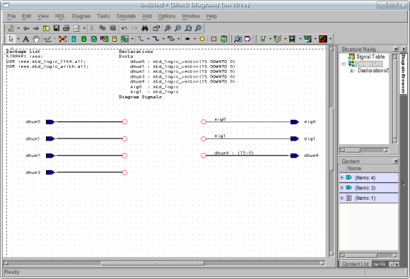
except using the Add Signal button,  ,
set to Signal Without Port. The Add Signal button is used
because two of the outputs, Zero and Overflow, are single
bit signals instead of multi-bit busses. Your Design should now look like
the figure below:
,
set to Signal Without Port. The Add Signal button is used
because two of the outputs, Zero and Overflow, are single
bit signals instead of multi-bit busses. Your Design should now look like
the figure below:
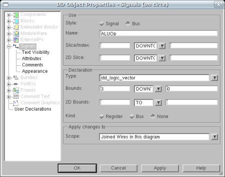
Since we do not want to use the default names for the signals and
busses, we need to assign our own. To do this, first make sure
that the selection tool, , is active
and then double-left-click on the bus wire dbus0. This will
bring up the Object Properties window opened to the signals
tab with the dbus0 signal selected. In the name field
replace dbus0 with ALUOp. In the declaration section,
set the bounds as 3 DOWNTO 0. Finally click OK. These changes
should be reflected on the signal name and the Declarations.
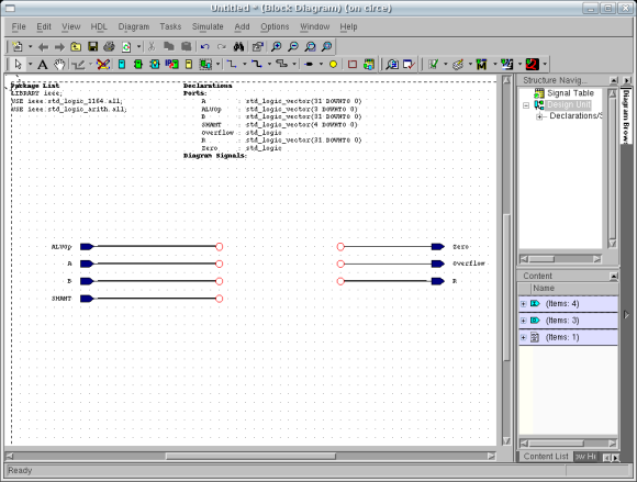
Change the rest of the signals and busses as shown in the following
table. The design should now resemble the figure below the table:
| Original Name |
New Name |
New Type |
New Bounds |
| dbus0 |
ALUOp |
std_logic_vector |
3 DOWNTO 0 |
| dbus1 |
A |
std_logic_vector |
31 DOWNTO 0 |
| dbus2 |
B |
std_logic_vector |
31 DOWNTO 0 |
| dbus3 |
SHAMT |
std_logic_vector |
4 DOWNTO 0 |
| dbus4 |
R |
std_logic_vector |
31 DOWNTO 0 |
| sig0 |
Zero |
std_logic |
NONE |
| sig1 |
Overflow |
std_logic |
NONE |
Once you have finished making all of the changes, you need to save the
Block Diagram by selecting File | Save from the menu or by clicking
the save button,  .
Select ALU as the library to save the design in, enter ALU as
the design unit name, and struct as the view name. This will save
the block diagram source data and also create a symbol for the design unit
with ports matching those in the block diagram.
.
Select ALU as the library to save the design in, enter ALU as
the design unit name, and struct as the view name. This will save
the block diagram source data and also create a symbol for the design unit
with ports matching those in the block diagram.
To see what effect our work thus far has had, go back to the
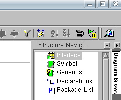
Design Manager window and double-click the ALU symbol. Click on
"Symbol" in the Structure Navigation pane if the "Interfaces" are being displayed.
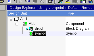
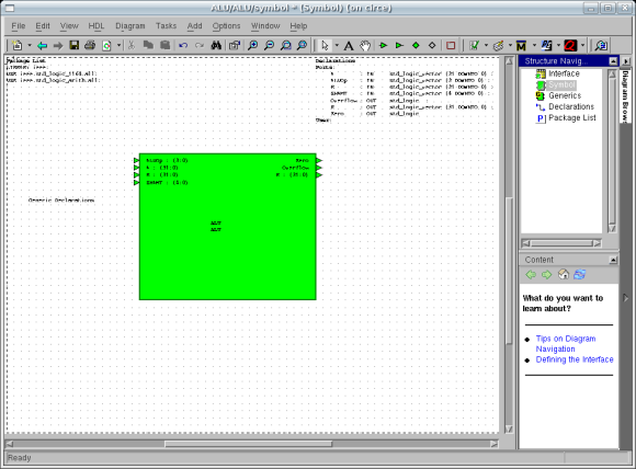
A window similar to that of the figure below should appear.
You should see input ports for A, B, ALUOp, and SHAMT and output
ports for Zero, Overflow, and R. We will modify the symbol later
to make it more readable. Once you have examined it, you may
close the window containing the symbol.
Now that we have examined the symbol, lets generate the VHDL code
for this file and see what is produced. First, back on the Design Manager, highlight
the ALU component. Then, click the Generate Through Components button,
 , from the available buttons

Note that this button can also be used from
a design editor window, such as the block diagram editor. In other words, you
could have also clicked this button the ALU block diagram editor. This will
generate HDL for the current design unit. A Log Window will appear.
If the log window reports any errors, ask the professor or TA for help.
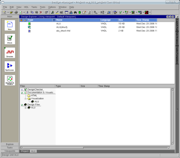
If the HDL generation completes with no errors, activate the
Design Manager window again. Make sure you have the
ALU library window open. Put the Design Manager in HDL mode by clicking
the HDL mode button:  . Click the button until
you see this view. Left-click on the plus sign to expand the tree under ALU and
you should see an entry for ALU_struct.vhd as in the figure below. Double-left-click
on this file to open it up in a VHDL editor.
. Click the button until
you see this view. Left-click on the plus sign to expand the tree under ALU and
you should see an entry for ALU_struct.vhd as in the figure below. Double-left-click
on this file to open it up in a VHDL editor.
The generated HDL code should be similar to the following:
-- VHDL Entity ALU.ALU.symbol
--
-- Created:
--          by - elenis.student (circe)
--          at - 19:44:16 12/20/06
--
-- Generated by Mentor Graphics' HDL Designer(TM) 2005.3 (Build 75)
--
LIBRARY ieee;
USE ieee.std_logic_1164.all;
USE ieee.std_logic_arith.all;

ENTITY ALU IS
   PORT(
      A        : IN     std_logic_vector (31 DOWNTO 0);
      ALUOp    : IN     std_logic_vector (3 DOWNTO 0);
      B        : IN     std_logic_vector (31 DOWNTO 0);
      SHAMT    : IN     std_logic_vector (4 DOWNTO 0);
      Overflow : OUT    std_logic;
      R        : OUT    std_logic_vector (31 DOWNTO 0);
      Zero     : OUT    std_logic
   );

-- Declarations

END ALU ;

--
-- VHDL Architecture ALU.ALU.struct
--
-- Created:
--          by - elenis.student (circe)
--          at - 19:44:16 12/20/06
--
-- Generated by Mentor Graphics' HDL Designer(TM) 2005.3 (Build 75)
--
LIBRARY ieee;
USE ieee.std_logic_1164.all;
USE ieee.std_logic_arith.all;


ARCHITECTURE struct OF ALU IS

   -- Architecture declarations

   -- Internal signal declarations


BEGIN

   -- Instance port mappings.

END struct;
|
Examine the generated HDL. The first section is the
Entity Declaration which describes I/O for our
black box design unit. The ports with connected and named
busses and signals which we placed on the block diagram
have been translated into ports in the entity declaration.
The second section of the generated HDL is the Architecture
Declaration for our struct architecture of the
ALU entity. So far, we have only placed ports and
signals or busses directly connected to those ports onto the
block diagram. Since the signals for these ports are inherently
declared in the architecture by their presence in the entity
declaration, there is nothing left to do. Hence, the architecture
is empty except for a few comments.
Note: Three easier methods to view the generated
HDL are to either select HDL | View Generated HDL
from the menu, right-clicking the object and click "View
Generated HDL" or by selecting the object and pressing CTRL + G.
Now that we have placed the ports on the block diagram and
looked at the simple VHDL generated by it, it is time to...
Add Subblocks to the Block Diagram.