
CSCE 211, Digital Logic Design
Circuit 1
Due: Tuesday, October 6, 2015
Goal: Design a loop counter with Arduino and 7-segment display.
Required:
| Arduino Chip | 1 |
| BreadBoard | 1 |
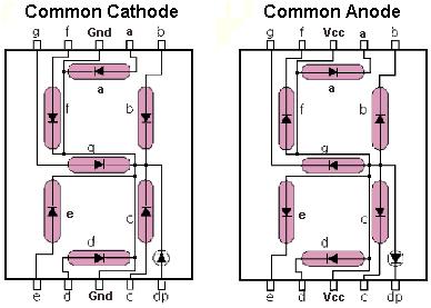
| Common anode 7-segment display | 1 |
| Resistors | 7 |
| USB Cable | 1 |
| 74LS47 | 1 |
| Jump wires | many |
Cook Manual
Setup Arduino
Setup: Download and decompress Arduino package.
Download: Go to the link http://arduino.cc/en/Main/Software to download Arduino software. (download the version corresponding to your OS)
Decompress software package: The file you downloaded may be a .zip package, which will require you to decompress it. Here is a decompressor software link if you need one. The decompress procedure may take a couple of minutes.
Install the driver: You can follow this link to install the driver.
After the package is decompressed, enter the extracted folder and execute arduino.exe and you will see the program editor started up.
Helloworld Program
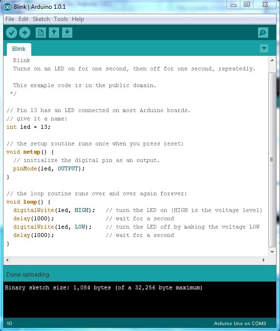
Click File->Examples->01.Basics->Blink on main menu. You just opened the example Blink program in the program editor.
Now connect Arduino to your computer by USB cable. You will see that the green power light on the chip is turned on.
Click "Upload" button (the circle with a rightbound arrow in it) on the program editor. It will upload the program to the chip and run it.
You will see that the orange LED begins to flash after the program has been uploaded.
Some explanations of the code
Function setup() is the initiator of the program. It will be called immediately after download is successful or the reset button is pressed. In the program, it calls function pinMode(led, OUTPUT) to set the pin 13 as a output pin. You can set multiple input/output pins in the setup() function.
Function loop() will be called after setup() returns. It will run over and over again until reset (when a new program is downloaded or the reset button is pressed). In the loop() function digitalWrite() is called to alternate the HIGH/LOW status on pin 13. The frequency of the flashing is lowered down to 1000ms by adding delay(1000) between digitalWrite().
Pin 13 is associated with the orange LED on the chip. The altering HIGH/LOW status of pin 13 causes the flashing of the orange LED.
Let's take a break and hooray for the success of setting up and testing the Arduino chip.
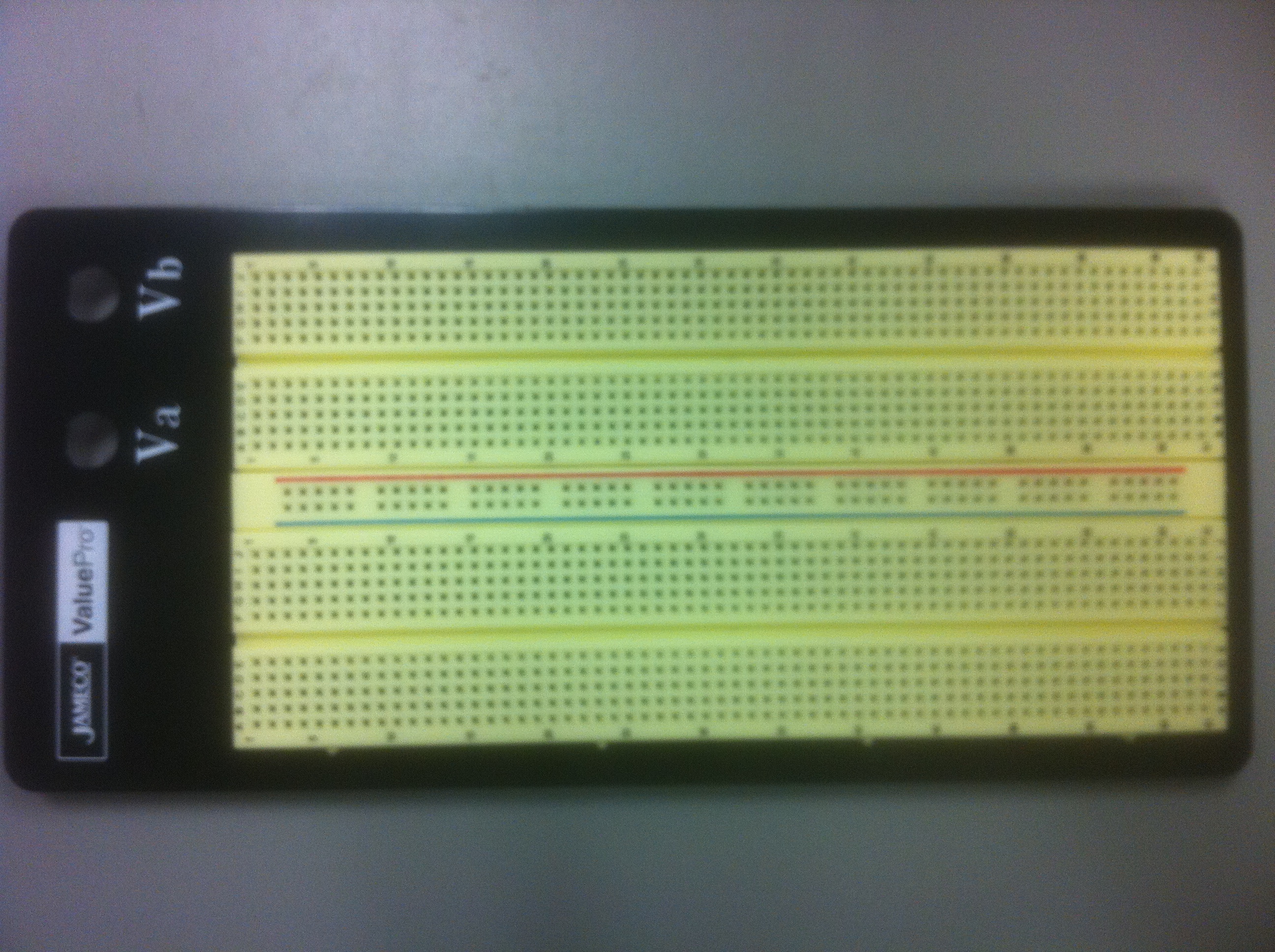
Bread board setup
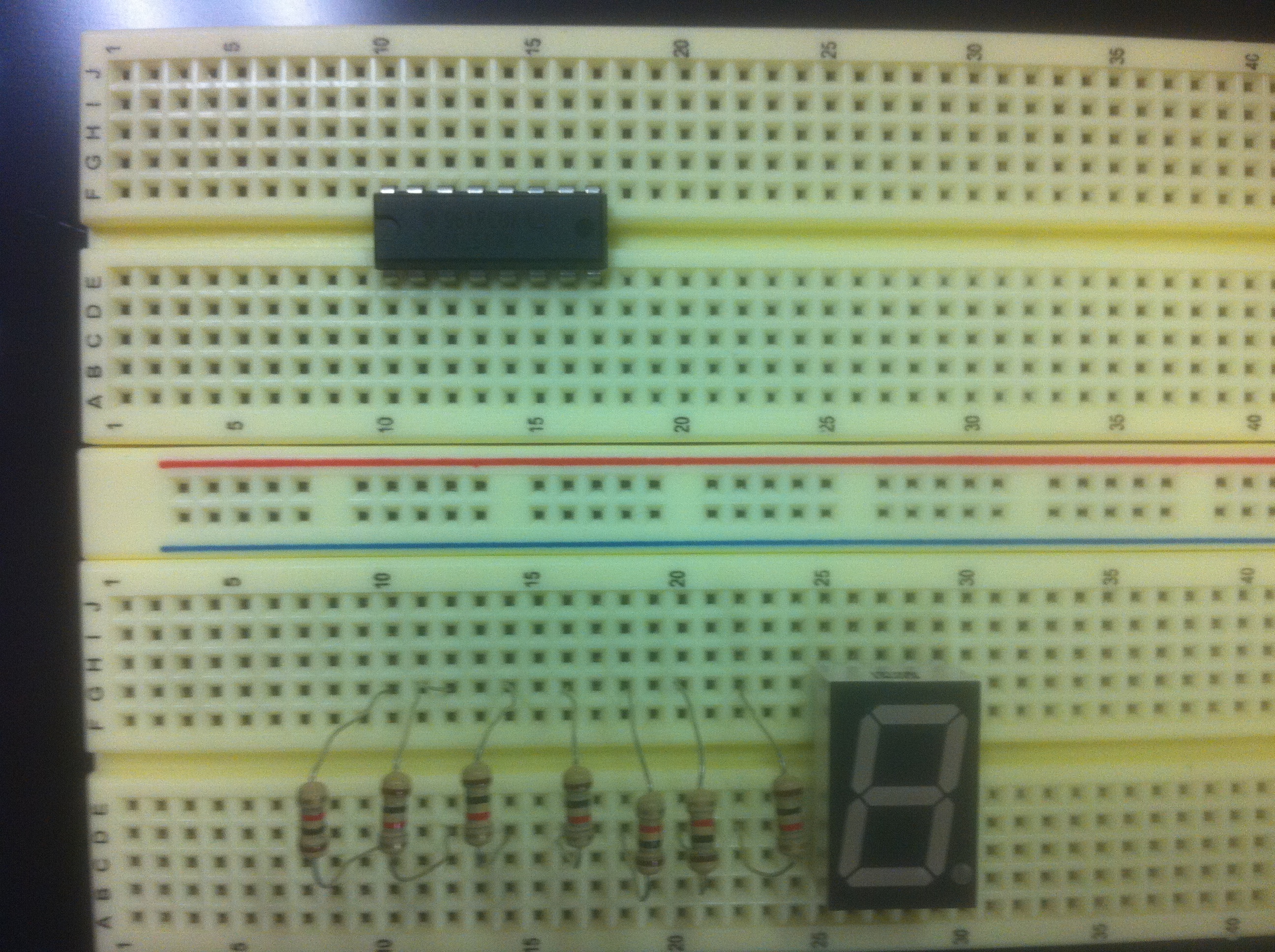
Put your bread board on an empty table with the 2-holes on the left hand side.
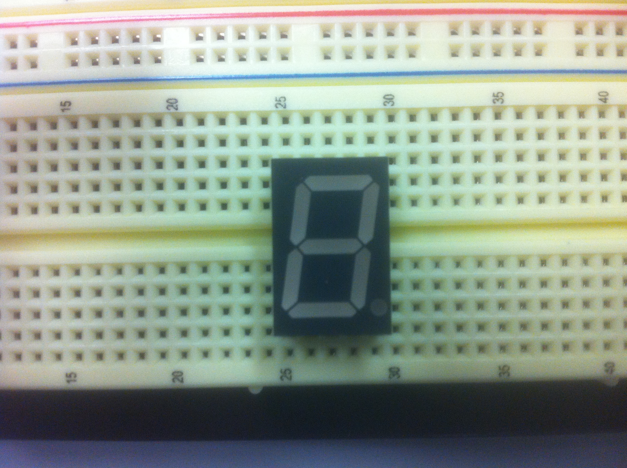
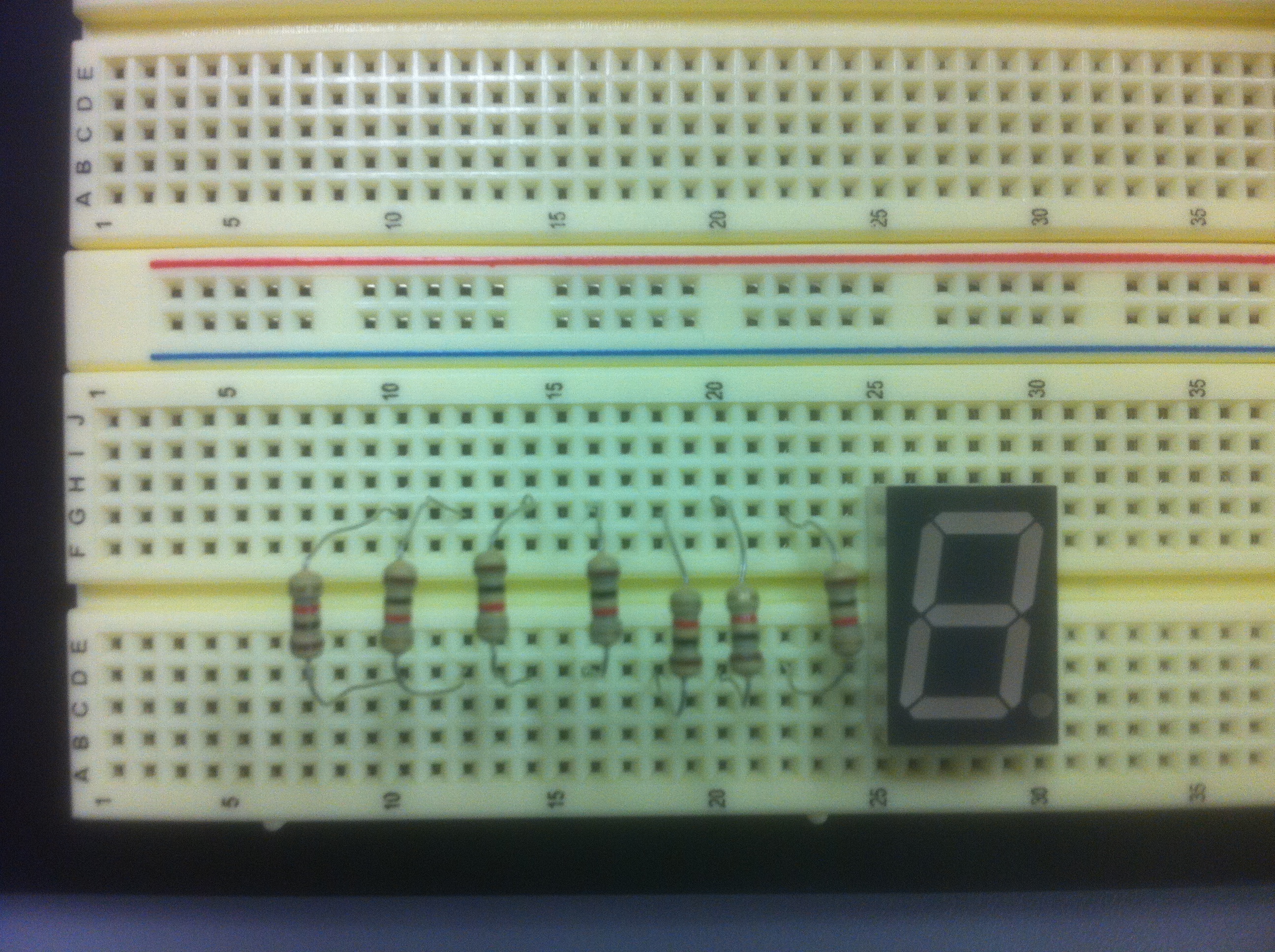
Plug in 7-segment display across lower row 25.
Plug 7 yellow resistors across lower row 22, 20, 18, 16, 14, 12, 10. Be careful that you should not let the wires touch each other; otherwise it may result in short circuit and overheat some parts.
Plug 74LS47 chip across the upper row 10-17 with the notch pointing toward the left.
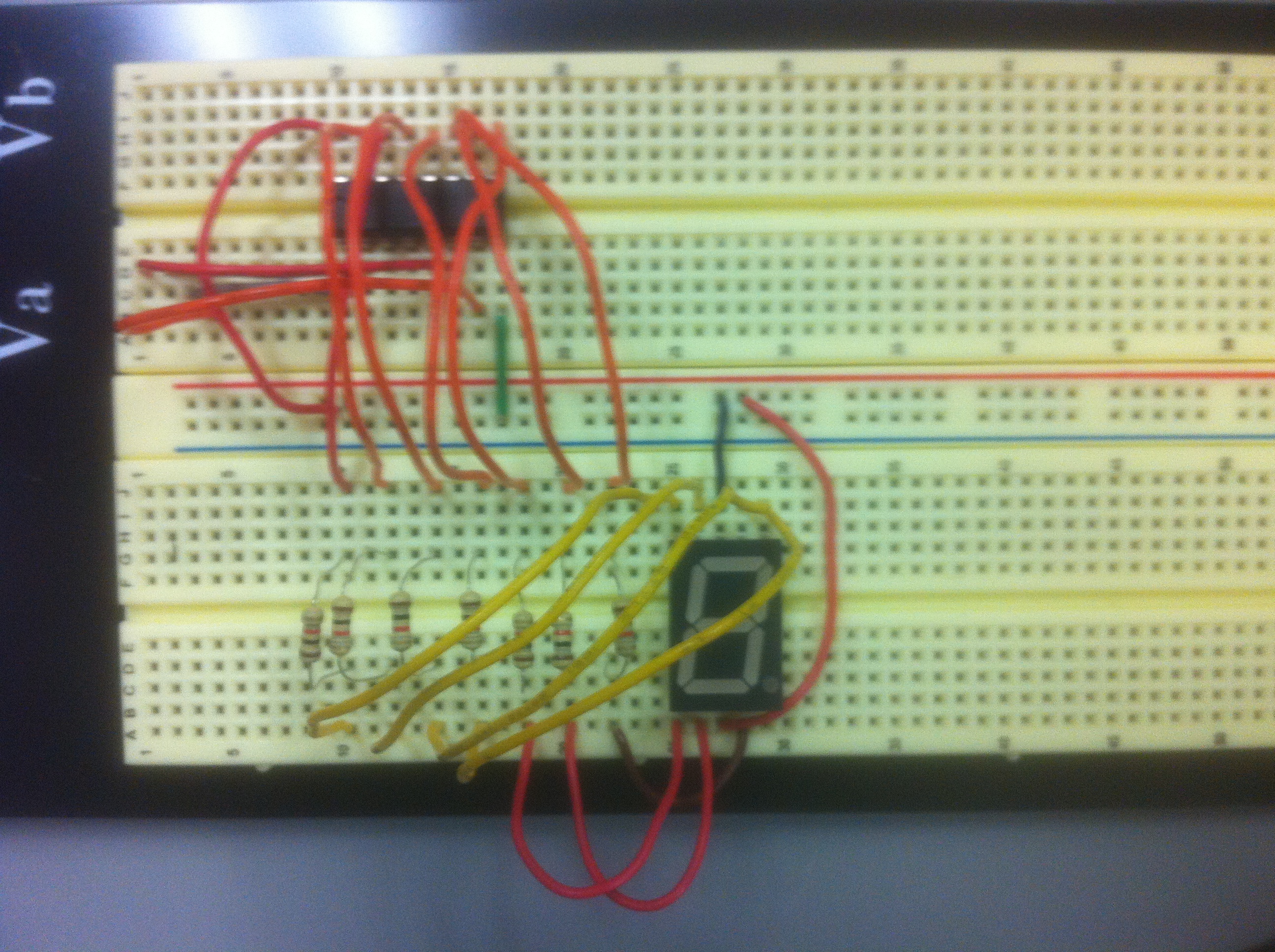
Connect jump wire from 22A to 28A, 20A to 26A, 18A to 25A, 16A to 29I, 14A to 28I, 12A to 26I, 10A to 25I, 27I (or 27A) to vcc (red line power bus).

Connect jump wire from 10H to vcc, 17B to gnd (blue line ground bus), 12H to 10J, 11H to 12J, 13H to 14J, 14H to 16J, 17H to 18J, 16H to 20J, 15H to 22J.
Connect jump wire from 15D to 1D, 11D to 2D, 10C to 3C, 16C to 4C.
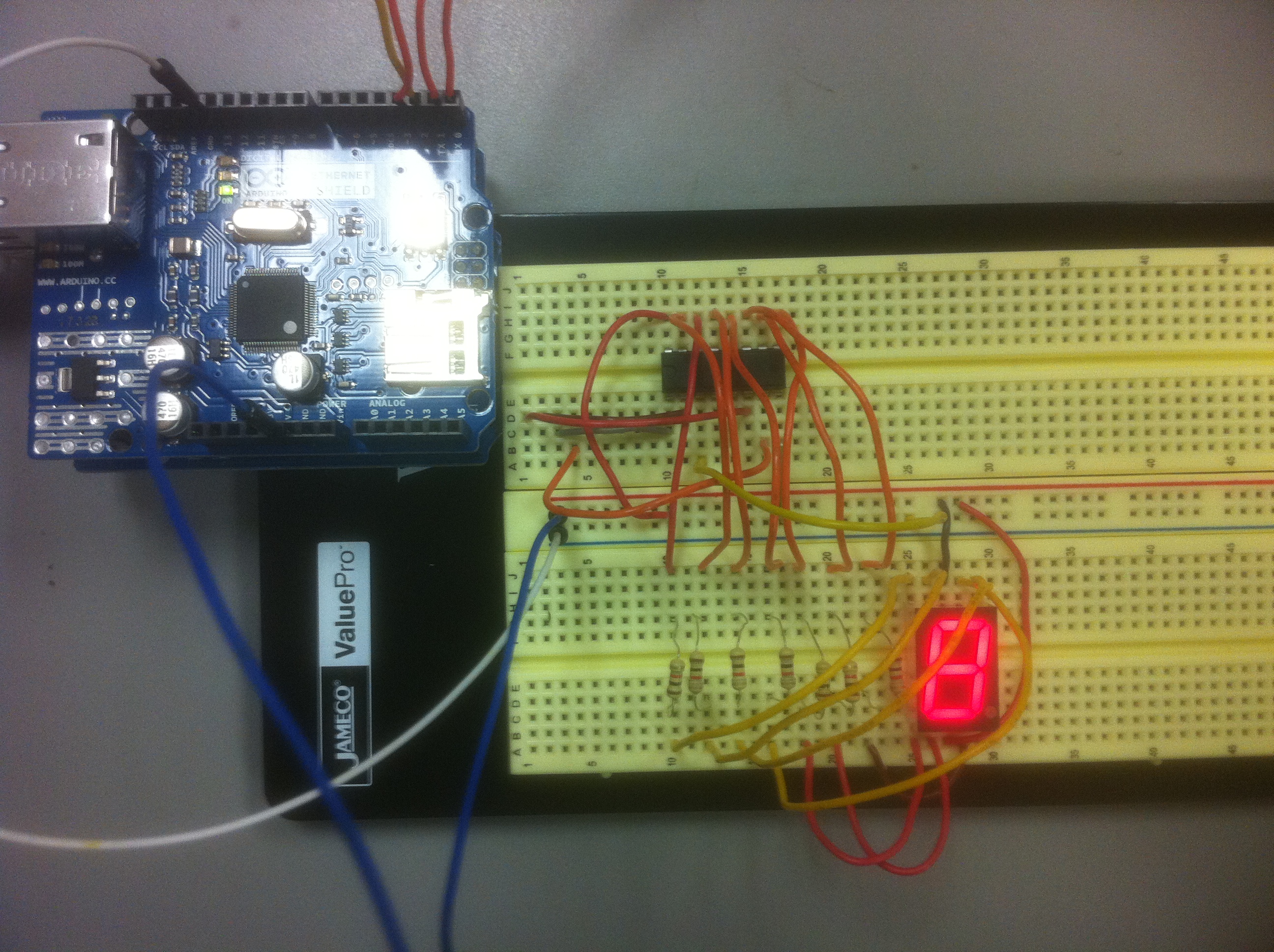
Power up the board and test lamp
Connect the Arduino to PC by USB cable.
Connect Pin "5V" on Arduino chip to vcc (red line power bus) on the bread board.
Connect Pin "GND" on Arduino chip to gnd (blue line ground bus) on the bread board.
Connect 12A to gnd (blue line ground bus).
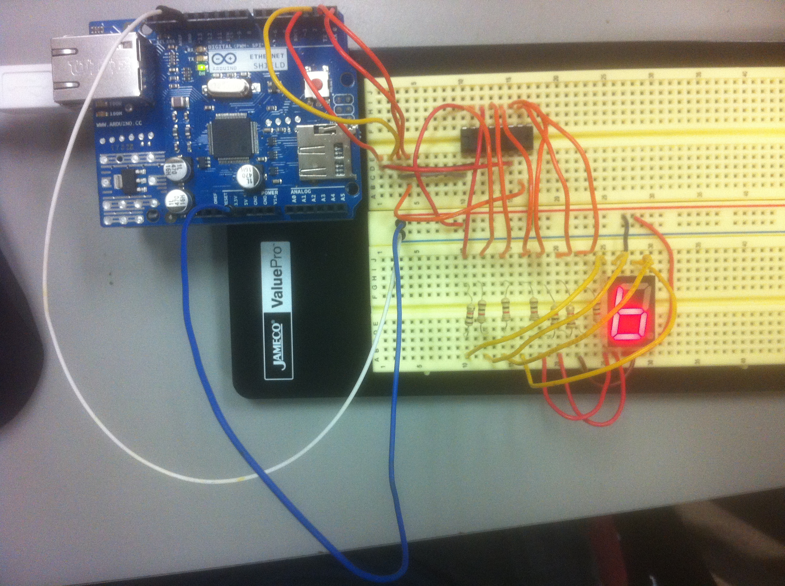
You will see the 7-segment LED showing "8" if your connections till now are all correct.
Programming the loop counter on Arduino
Remove the connection between 12A and gnd. (The 7-segment display will be off after this step. Don't be panic; it is normal)
Start the Arduino programming editor.
Write the following code into the editor.
// Output pins.
static int output[] = {0,1,2,3};
// 8421 code lookup table.
static int segs_encoding[][4] =
{{0,0,0,0},
{0,0,0,1},
{0,0,1,0},
{0,0,1,1},
{0,1,0,0},
{0,1,0,1},
{0,1,1,0},
{0,1,1,1},
{1,0,0,0},
{1,0,0,1}};
// Outputs an 8421 decimal digit on the output pins from
// base to base + 3 in big endian order.
void show(int base, int num) {
for (int i = 0; i < 4; ++i) {
if(segs_encoding[num][i] == 1) {
digitalWrite(base + 3 - i , HIGH);
} else {
digitalWrite(base + 3 - i , LOW);
}
}
}
// Output a decimal value.
void show_decimal(int num) {
show(0, num);
}
// the setup routine runs once when you press reset:
void setup() {
for (int i = 0; i < 4; ++i)
pinMode(i, OUTPUT);
}
// the loop routine runs over and over again forever:
void loop() {
static int i = 0;
show_decimal(i);
delay(1000);
// Increases the counter.
++i;
if (i == 10)
i = 0;
}
After the code is typed into the editor, click "Save" to save your project. Remember the folder where you save the project for retrieving it in the future and save your program frequently during code writing.
Connect Pin "0->RX" on chip to 4E on bread board.
Connect Pin "TX->1" on chip to 3E on bread board.
Connect Pin "2" on chip to 2E on bread board.
Connect Pin "~3" on chip to 1E on bread board.
After the project is saved, click "Upload". After the uploading is successful, you will see the 7-segment display begins to count.
Circuit Project Requirements
This circuit project will count for 3 points toward your final grade.
To get full points, you need to show the correct result of (1) lamp test and (2) the loop counter.
If you show only either (1) or (2), you will receive half of the points.
Bonus
You will get 0.5 bonus points if you show a 2-digit loop counter using two 7-segment displays and two 74LS47 chips. The loop counter counts from 00 to 59 and back to 00. Set the counting delay to be 1000 ms.
Useful Links
Pin map of common anode 7-segment display