CSCE 211, Digital Logic Design
Circuit 2
Due: Thursday, October 24, 2013
Goal: Design an Arduino thermometer. It reads in the temperature value from a DHT11 sensor and output the value to two 7-segment displays.
Required:
| Arduino board | 1 |
| Breadboard | 1 |
| Common anode 7-segment display | 2 |
| Resistors | 14 |
| USB Cable | 1 |
| 74LS47 | 2 |
| Red LED | 1 |
| Green LED | 1 |
| Yellow LED | 1 |
| Piezo Speaker | 1 |
| Jump wires | many |
Cook Manual
Test temperature sensor
The circuit package includes a DHT11 temperature sensor. There are 4 pins on the temperature sensor. They are "vcc", "readout", "unused" and "gnd" from left to right. Connect the 4 pins to the breadboard so that they are inserted into 4 adjacent columns on the breadboard.
The "vcc" pin should be connected to +5v (you can connect to either the vcc pin on the Arduino board, or any hole on the red line power bus if you have connected the vcc to the red line).
The "gnd" pin should be connected to gnd (you can connect to either the gnd pin on the Arduino board, or any hole on the blue line ground bus if you have connected the gnd to the blue line).
The "readout" pin outputs the analog temperature / humidity value.
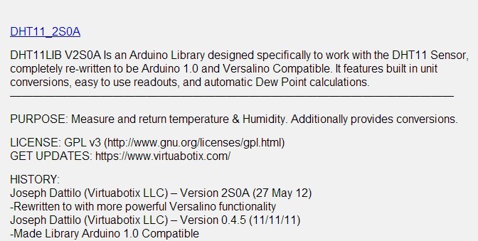
Download: Go to link https://www.virtuabotix.com/?attachment_id=257 to download the library file for the temperature sensor. Click DHT11_2S0A to download the library file.
The library file you downloaded is a compressed archive. Decompress it and enter the extracted folder "DHT11_2S0A". Copy the folder "DHT11" into the path <your_arduino_path>/libraries.
For how to use the sensor with Arduino, refer to this page https://www.virtuabotix.com/reference/index.php?title=DHT11_Wiki
Testing the sensor: Start Arduino program editor.
Click "File->Examples->DHT11->dht11_functions". It will open the temperature sensor program example.
Power up the sensor and the Arduino board.
Connect the digital pin 2 on Arduino board to the "readout" pin of the temperature sensor.
Upload the program.
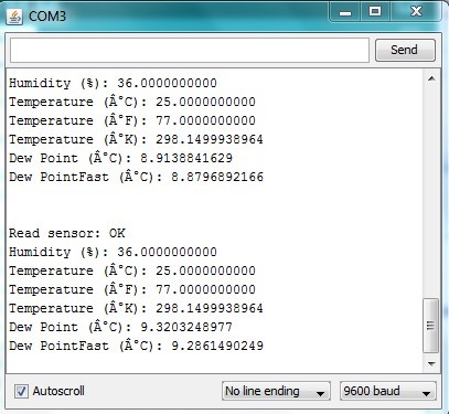
After the program is successfully uploaded, click the "Serial Monitor" button (the amplifier icon of the top-right corner) to open the serial monitor terminal. You will see the temperature and humidity values are updated and scrolled on the terminal.
Some explanations of the code
### Code ###
#include <dht11.h>
dht11 DHT11;
void setup()
{
DHT11.attach(2);
Serial.begin(9600);
Serial.println("DHT11 TEST PROGRAM ");
Serial.print("LIBRARY VERSION: ");
Serial.println(DHT11LIB_VERSION);
}
void loop()
{
Serial.println("\n");
int chk = DHT11.read();
Serial.print("Read sensor: ");
switch (chk)
{
case 0: Serial.println("OK"); break;
case -1: Serial.println("Checksum error"); break;
case -2: Serial.println("Time out error"); break;
default: Serial.println("Unknown error"); break;
}
Serial.print("Humidity (%): ");
Serial.println((float)DHT11.humidity, DEC);
Serial.print("Temperature (��C): ");
Serial.println((float)DHT11.temperature, DEC);
Serial.print("Temperature (��F): ");
Serial.println(DHT11.fahrenheit(), DEC);
Serial.print("Temperature (��K): ");
Serial.println(DHT11.kelvin(), DEC);
Serial.print("Dew Point (��C): ");
Serial.println(DHT11.dewPoint(), DEC);
Serial.print("Dew PointFast (��C): ");
Serial.println(DHT11.dewPointFast(), DEC);
delay(2000);
}
### Code ###
The program first initializes a dht11 instance by declaring it at the beginning (outside all the functions).
dht11 DHT11;
In the setup function, you need to call the initializer of the dht11 instance.
DHT11.attach(port_num).
The port_num is the ID of the pin on the Arduino board which is connected to the "readout" pin on the sensor.
To read value from the sensor, you need to call DHT11.read() and save the value into an integer variable.
How to use the Piezo Speaker
First take a look at the Piezo Speaker in your circuit project kit.
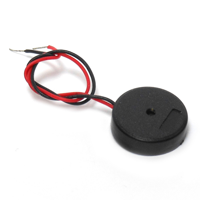
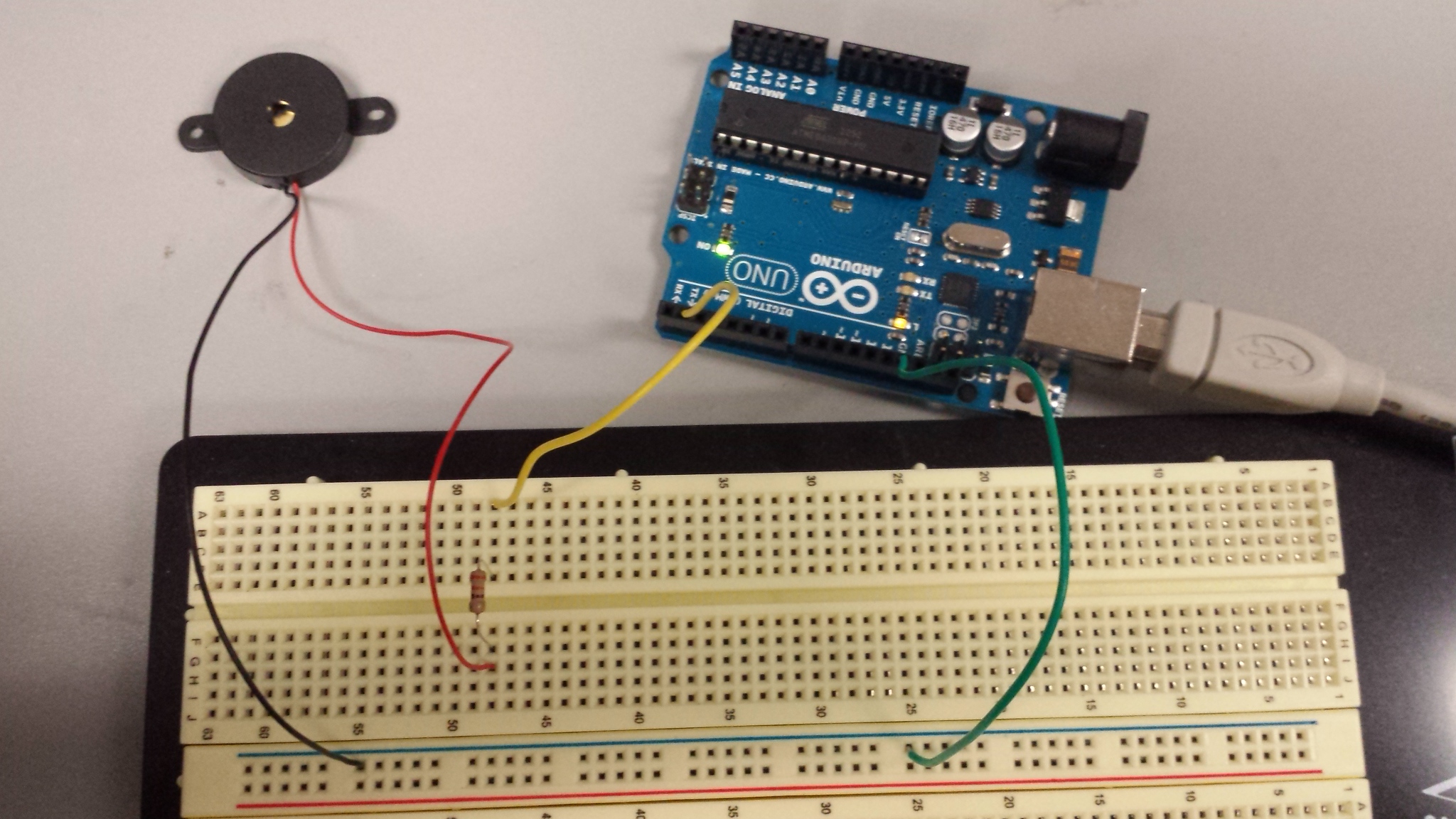
There are two wires out of a Piezo Speaker, one black wire and one red wire. To make the speaker work, the black wire should be connected to the ground line on the breadboard, and the red wire to the source of the digital sound signal. In the following example, we use digital pin 1 on Arduino board to drive the speaker. Therefore, connect the red wire to pin 1 through a resistor.
Copy the following code to the Arduino program editor and run it. After the code is uploaded to the Arduino board, press the reset button and the speaker will play a short piece of music.
/*
Melody
Plays a melody
circuit:
* 8-ohm speaker on digital pin 8
created 21 Jan 2010
modified 30 Aug 2011
by Tom Igoe
This example code is in the public domain.
http://arduino.cc/en/Tutorial/Tone
*/
#define NOTE_B0 31
#define NOTE_C1 33
#define NOTE_CS1 35
#define NOTE_D1 37
#define NOTE_DS1 39
#define NOTE_E1 41
#define NOTE_F1 44
#define NOTE_FS1 46
#define NOTE_G1 49
#define NOTE_GS1 52
#define NOTE_A1 55
#define NOTE_AS1 58
#define NOTE_B1 62
#define NOTE_C2 65
#define NOTE_CS2 69
#define NOTE_D2 73
#define NOTE_DS2 78
#define NOTE_E2 82
#define NOTE_F2 87
#define NOTE_FS2 93
#define NOTE_G2 98
#define NOTE_GS2 104
#define NOTE_A2 110
#define NOTE_AS2 117
#define NOTE_B2 123
#define NOTE_C3 131
#define NOTE_CS3 139
#define NOTE_D3 147
#define NOTE_DS3 156
#define NOTE_E3 165
#define NOTE_F3 175
#define NOTE_FS3 185
#define NOTE_G3 196
#define NOTE_GS3 208
#define NOTE_A3 220
#define NOTE_AS3 233
#define NOTE_B3 247
#define NOTE_C4 262
#define NOTE_CS4 277
#define NOTE_D4 294
#define NOTE_DS4 311
#define NOTE_E4 330
#define NOTE_F4 349
#define NOTE_FS4 370
#define NOTE_G4 392
#define NOTE_GS4 415
#define NOTE_A4 440
#define NOTE_AS4 466
#define NOTE_B4 494
#define NOTE_C5 523
#define NOTE_CS5 554
#define NOTE_D5 587
#define NOTE_DS5 622
#define NOTE_E5 659
#define NOTE_F5 698
#define NOTE_FS5 740
#define NOTE_G5 784
#define NOTE_GS5 831
#define NOTE_A5 880
#define NOTE_AS5 932
#define NOTE_B5 988
#define NOTE_C6 1047
#define NOTE_CS6 1109
#define NOTE_D6 1175
#define NOTE_DS6 1245
#define NOTE_E6 1319
#define NOTE_F6 1397
#define NOTE_FS6 1480
#define NOTE_G6 1568
#define NOTE_GS6 1661
#define NOTE_A6 1760
#define NOTE_AS6 1865
#define NOTE_B6 1976
#define NOTE_C7 2093
#define NOTE_CS7 2217
#define NOTE_D7 2349
#define NOTE_DS7 2489
#define NOTE_E7 2637
#define NOTE_F7 2794
#define NOTE_FS7 2960
#define NOTE_G7 3136
#define NOTE_GS7 3322
#define NOTE_A7 3520
#define NOTE_AS7 3729
#define NOTE_B7 3951
#define NOTE_C8 4186
#define NOTE_CS8 4435
#define NOTE_D8 4699
#define NOTE_DS8 4978
// notes in the melody:
int melody[] = {
NOTE_C4, NOTE_G3,NOTE_G3, NOTE_A3, NOTE_G3,0, NOTE_B3, NOTE_C4};
// note durations: 4 = quarter note, 8 = eighth note, etc.:
int noteDurations[] = {
4, 8, 8, 4, 4, 4, 4, 4 };
void setup() {
// iterate over the notes of the melody:
for (int thisNote = 0; thisNote < 8; thisNote++) {
// to calculate the note duration, take one second
// divided by the note type.
//e.g. quarter note = 1000 / 4, eighth note = 1000/8, etc.
int noteDuration = 1000/noteDurations[thisNote];
tone(1, melody[thisNote],noteDuration);
// to distinguish the notes, set a minimum time between them.
// the note's duration + 30% seems to work well:
int pauseBetweenNotes = noteDuration * 1.30;
delay(pauseBetweenNotes);
// stop the tone playing:
noTone(1);
}
}
void loop() {
// no need to repeat the melody.
}
The tone() function is used to sound the speaker. The first parameter of the tone() function is the output pin that is connected to the signal input (red wire) of the speaker. The second and third parameters are the sounding frequency (tone) and the sounding latency (duration).
Breadboard setup
Set up two 7-segment displays, two 74LS47 chips, and 14 resistors on the breadboard, and set up the connections between the two 7-segment displays and the two 74LS47 chips. (You can refer to the instructions in Circuit Project 1 and the pin maps of 7-segment display and 74LS47 chip to see how to correctly set up the connections between the 7-segment displays and the 74LS47 chips.)
Connect digital pins (3,4,5,6) and (7,8,9,10) to the inputs (A3,A2,A1,A0) of the two 74LS47 chips respectively. The two set of pins (3,4,5,6) and (7,8,9,10) are used to output the two-digit 8421 BCD temperature value from the Arduino board to the 74LS47 decoder.
The temperature values are read in from the connection between "readout" and Arduino pin 2.
If you are honors section students, connect Piezo Speaker to the Arduino board pin 13. In the code, you also need to change the parameter of tone() and noTone() functions to reflect the pin number change.
Programming
Refer to the example program to write your project program which can continuously read in temperature values and output the two-digit Fahrenheit temperature value to the two 7-segment displays. If you are honors section students, you also need to insert additional code such that if the temperature is higher than 80F or lower than 70F, the Piezo Speaker will repeatedly sound an alarm (You may decide what the alarm sounds like).
Circuit Project Requirements
This circuit project will count for 3 points toward your final grade.
Regular Section
To get full points, you need to show the correct indoor temperature. Correctness of each of the 7-segment LED will count for half of the credits.
Honors Section
In addition to showing the correct indoor temperature, you are also required to add a temperature alert system which includes a red LED, a yellow LED and a green LED on the board. Turn on the corresponding LED according to the following table:
| temperature (F) | red | yellow | green | alarm |
| [70, 80] | 0 | 0 | 1 | no |
| [65, 70) or (80, 85] | 0 | 1 | 0 | yes |
| else | 1 | 0 | 0 | yes |
How to light up an LED
Each LED has 2 legs. To light it up, the current must flow into the longer one and flow out from the shorter one. The following is the order of the connection which lights up a LED:
Digital HIGH --> longer leg of LED --> (through the LED) --> shorter leg of LED --> resistor --> gnd
To control the LED by Arduino, you should connect an output pin on the Arduino board to the longer leg of the LED. Setting the output = HIGH will turn on the LED, and setting output = LOW will turn off the LED.
Extra credit for regular section
If your design meets the honors section requirement, you will receive one extra point toward your final grade.
Useful Links
Pin map of common annode 7-segment display